
RVA Traverse on the discharge of a coil.
Justifying the possible need for the use of ANSI/ASHRAE Standard 111-2008's procedure for measuring airflow on the discharge of a coil and simplifying its application.

We all know the purpose for taking field-measured airflow rates, which “is used for the certification of the performance of new systems, improvement or redesign of existing systems for efficient energy performance, and documentation of a system's performance for the purpose of analyzing maintenance and quality problems.”1 For me, I’m always looking for new ways to analyze the performance of air-handling units, as it has been stated that nothing “in TAB work is as critical as determining the unit’s overall performance.”2 I’m always thinking “I need a backup to the backup, a way to verify the unit’s performance if all else fails.” Yet, even when I explain this paranoia, every time I bring up that ANSI/ASHRAE Standard 111-2008 has a procedure for measuring airflow on the discharge side of a coil, every balancer says the same thing.
“What’s the point of that? Just traverse it.”
Often, totaling an air-handler with a pitot tube traverse is sufficient and pitot tube traverses are preferred for a reason—they’re extremely reliable and relatively easy to set up and perform properly.
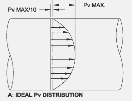
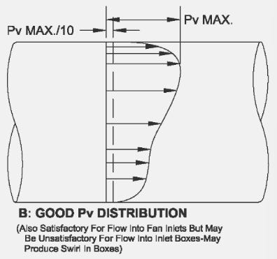
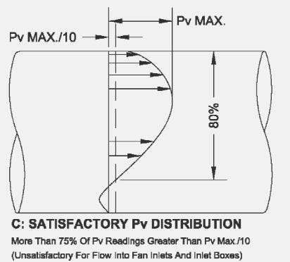
However, pitot tube traverses have their own limitations. ANSI/ASHRAE Standard 111-2008 also states that a pitot tube is unreliable when greater than 25% of the values are less than 10% of the maximum velocity reading. NEBB standards (2019) adopt this same standard for judging the quality of a traverse, stating that the “accuracy of a traverse is determined by the availability of a suitable location to perform a traverse. Suitability of the location is determined by quality of the data measured… acceptability of the traverse plan is determined solely by the quality of the data, and not necessarily by the location of the traverse plane.”3 Thus, the quality of the traverse plane is determined by the quality of the data. This is more clearly shown when we look at possible velocity profiles, as shown in ANSI/ASHRAE Standard 111-2008.
We can see an ideal, a good, and a satisfactory traverse plane distribution here4:
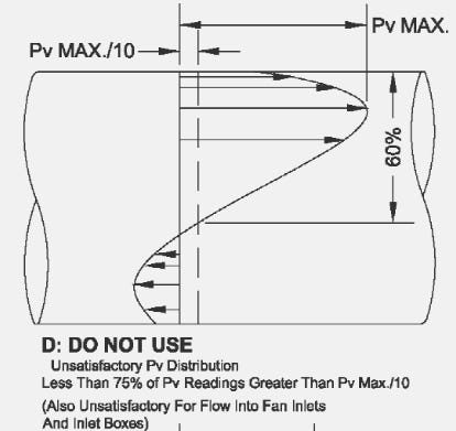
Below, here are some examples of unsatisfactory traverse planes which cannot be used, as per NEBB and ASHRAE standards:
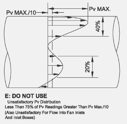
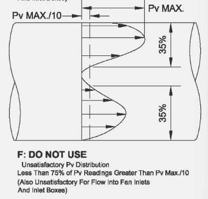
So, the question becomes, what do you do for measuring total flow when you have a traverse plane that is unsatisfactory and is unable to be used?
One answer may be to use static pressure readings across various components of the air-handling unit. This can be done by finding the design static pressure drop across a component, like a heating coil. Through looking up manufacturers specifications, let’s say you find that at 2000 CFM the drop across the coil will be 1.00 INWC. From here, fan law two could be used to determine airflow. Say we had a drop of 1.54 INWC:
CFM = 2000 x √(1.54 / 1.00) = 2482 CFM
There is one major problem with this—the distinction between field measurements and laboratory measurements. Bevirt says, “System airflow measurements will be very dependent on having good locations for Pitot tube traverses. If several diameters of straight duct are available, the results should be good. Accurate static pressure readings are the most difficult readings to get in the field, so they are usually the least accurate.”5 The static rule given by the manufacturer was determined in a laboratory, where static readings can be reliably measured. But we all know that reliable measurements in the field are a different story.
This static reliability issue makes sense when we look at what affects the performance of the Pitot tube and its sensitivity to static pressure. “Acceptance of the standard Pitot static tube is due to its accuracy in correct determination of the static pressure. The total pressure is not affected by yaw or angularity up to approximately 8° on either side of parallel flow. The static pressure, however, is extremely sensitive to direction of flow.”6 In other words, the Pitot tube must be parallel to flow or else the static reading is incorrect. This sensistivity to the direction of flow is why you should never insert the tube of your manometer into the hole. “SP measurement are properly performed with a calibrated micromanometer and a Pitot tube or a static probe. Simply inserting a tube end into an airstream without a static tip or Pitot tube probe may result in significant errors.”7
I do not have personal documentation of variations in either the static pressure due to yaw or angularity nor how off the static pressure readings, using fan law two, can be off from quality Pitot tube duct traverse, but my gut tells me that within the turbulent, non-uniform flow of an air-handling unit, any static pressure reading should be suspect. And this should make us pause. If “the accuracy of the measurement” of total airflow “is important to designers, owners, manufacturers, and installer of the system”8, then why are we playing around with a method which is completely instable and difficult to verify the quality of?
In the abstract to their 1990 paper, Sauer and Howell state that a “procedure for measuring the volume flow rate of air through a heating or cooling coil is presented. When a pitot tube traverse is impossible or impractical, the rotating vane anemometer procedure described and verified here will provide volume flow rates with similar uncertainty in the results. The rotating vane anemometer procedure was shown to produce estimates of volume flow rate at coil faces to within ±7%. The procedure is valid in a velocity range of 100 to 1100 fpm, and upstream disturbances such as elbows, partially blocked coils, dampers, and fan blasts had virtually no effect on the accuracy of using the K-factor procedure as long as the measured velocities were positive and relatively uniform.”9
Through a large sample size of tests, they were able to develop correction factors for any coil, regardless of measured air velocity, number of rows of tubes, number of coil fins, tube spacing, and tube diameter. They were able to do this by developing the correction factor based on all of these variables. The major issue is that the math gets tedious and cumbersome.
It starts out simple:
Q = A x MV x K
where
Q = volume flow rate
A = coil face area
MV = measured average velocity at the downstream coil face using a rotating vane anemometer. MV is shown below:
Vi = measured velocity at a specific position on the downstream coil face
n = the number of positions where V is measured
K = the correction factor.
ASHRAE Standard 111-2008 more easily shows how to develop K, at this point, and we can begin to see why this method becomes tedious.
Where
ROWS = number of tube rows in the coil
FPI = fins per inch
SP = tub center to center spacing, in.
OD = outside diameter of tube, in.
K = conversion factor
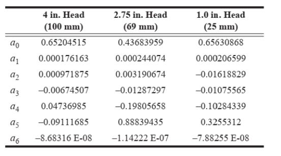
a0 through a6 are numbers developed in the laboratory to account for differences in head sized of various RVAs.
Going back to the k equation for a minute, we can see something disheartening. The factor MV is taken into account. This means that the K must be recalculated every time we take a traverse. This makes performing this method impractical and nearly impossible for the average balancer armed with their trusty calculator.
However, I’ve worked to fix that. In this post, at the bottom, I’ve attached a first draft of my calculator for this equation. A couple things to take note on. I used the following equation to correct for SCFM to ACFM.
where
ACFM = Actual Cubic Feet per Minute
SCFM = Standard Cubic Feet per Minute
Pstd = standard absolute air pressure (psia)
Pact = absolute pressure at the actual level (psia)
Psat = saturation pressure at the actual temperature (psi)
Φ = Actual relative humidity
Tact = Actual ambient air temperature (°R)
Tstd = Standard temperature (°R)
Note that Rankine is automatically factored from your °F input.
To estimate the pressure based on altitude, I used:
I did this by converting the altitude in feet to meters and then converting the output of pascals to PSIA. This gave me Pact.
Psat was calculated with the following equation:
And all of this was multiplied by 0.14503774 to convert it from kilopascals to PSI.
With these number calculated in the spreadsheet, the spreadsheet automatically takes into account corrections for the flow based on local temperatures (if the temperatures and relative humidities are not uniform on the discharge of the coil) and corrects them. They are then calculated into MV which feeds into the K. This, along with the proper selection of the RVA size being used, makes this method less tedious by a mile.
The calculator also tells you where the reads are to be taken on the coil. Details about how these points are calculated can be found in the ASHRAE papers and in the original works from Sauer and Howell. I’d strongly recommend you read all of these papers and understand them in their entirety before attempting to even look through the below calculator, let alone using it.
If you use this calculator, please give me feedback. If I made an error, let me know. This is meant to be a baseline for you to use in your own balancing endeavors.
Failed to render LaTeX expression — no expression found
Sauer and Howell, “Airflow Measurements at Coil Faces with Vane Anemometers: Statistical Correlation and Recommended Field Measurement Procedure.”, 1990, 502.
Andrew P. Nolfo, Designing for Proper Testing, Adjusting and Balancing of Air and Hydronic Systems, “The NEBB Professional”, July, 2012, 15.
“NEBB Procedural Standard for Testing, Adjusting, and Balancing of Environmental Systems”, 2019, 26.
“ASHRAE Standard 111-2008 (RA2017) Measurement, Testing, Adjusting, and Balancing of Building HVAC Systems”, 66. See also, “NEBB Procedural Standard for Testing, Adjusting, and Balancing of Environmental Systems”, 2019, 26.
Bevirt, “Environmental Technological Systems”, 1999, 6.24.
“ASHRAE Standard 111-2008 (RA2017) Measurement, Testing, Adjusting, and Balancing of Building HVAC Systems”, 4.
“NEBB Procedural Standards for Testing, Adjusting, and Balancing of Environmental Systems”, 2019, 37.
Sauer and Howell, “Airflow Measurements at Coil Faces with Vane Anemometers: Statistical Correlation and Recommended Field Measurement Procedure.”, 1990, 502.
Sauer and Howell, “Airflow Measurements at Coil Faces with Vane Anemometers: Statistical Correlation and Recommended Field Measurement Procedure.”, 1990, 502.